Quantcast
Channel: Solutions – Alicat Scientific
Viewing all 50 articles
Browse latest View live

Integrate a fast flow controller into your networked system

$
0
0
Ethernet/IP and DeviceNet now available on mass flow controllers, meters and pressure controllers
Ethernet/IP and DeviceNet

Two new networking industrial protocols compatible with Alicat Instruments.

What’s cooler than having the world’s fastest lab-quality flow or pressure control device?

Did you think, “Networking that baby into an industrial process!”? Well, you read our minds, because so did we! … That’s so spooky!

Connecting flow and pressure controllers or meters to an industrial i/o system is easier than ever with the addition of Ethernet/IP or DeviceNet protocols. This brings the available list of protocols on Alicats to four:

  • Modbus
  • PROFIBUS
  • Ethernet/IP
  • DeviceNet

The new protocols are available on our mass flow controllers, series mass flow meters, and pressure controller products, as well as their versions in stainless, liquids, high pressure, high flow, dual valve, Whisper low pressure drop, and the like.

To get a protocol on your Alicat device, simply request the option when you order. The protocols are not available as retrofits. Visit our product options page to find additional information about the protocols available. Or ask our applications engineers. They love solving problems.

Have questions about using protocols?


Sign me up for the occasional newsletter.
Please leave this field empty.

The post Integrate a fast flow controller into your networked system appeared first on Alicat Scientific.


Improved Process Gas Control Optimizes Reactive Sputtering

$
0
0

Customized valve response algorithms in flow controllers produce better films, with more control of the target’s transition state.

Reactive Sputtering

800px-piiid_knee_agtarget_iot-labeled

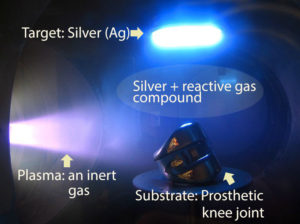
Reactive Sputtering is a type of Physical Vapor Deposition process used to create thin film vacuum coatings. The process deposits a compound material coating on a substrate by introducing a reactive gas, such as O2 or N2, into a plasma typically generated using an inert gas, such as Argon. The reactive gas is activated by the plasma, and then chemically reacts with a “target”—normally consisting of metals, alloys or ceramics—producing a coating material which is deposited on a substrate. The resultant oxide, nitride or carbide coating imparts properties such as low emissivity or durability to the substrate that is coated.

Reactive Sputtering deposition is very commonly used in manufacturing and R+D processes, such as:

  • Flat-panel displays for televisions and cell phones
  • Photovoltaic coatings on solar cells
  • Optical coatings on sunglasses
  • Decorative coatings on hardware and automotive components
  • Insulating coatings on architectural glass

Alicat mass flow controllers are compatible with the most common reactive gases. Those gases—and some of their typical compounds—are:

  • Oxygen (O2) – creating oxides such as Al2O3, SiO2, TiO2, ITO (Indium Tin Oxide)
  • Nitrogen (N2) – producing nitrides such as TiN, ZrN, CrN
  • Acetylene (C2H2) or Methane (CH4) – for diamond-like carbon films

Controlling the sputtering process

By controlling the amount and timing of reactive gas flows, deposition rates and film properties can be adjusted with some precision. Using flow control does not require active feedback, but the deposition rate is lower compared to closed-loop control, and film properties can be less than optimal.

A closed-loop control of partial pressure provides higher deposition rates versus flow control and the film properties are improved. But closed-loop control requires active feedback control, increasing the complexity and expense of the process. Equally important is that the system respond swiftly and precisely to the feedback, to ensure a good coating. Since reactions are electrochemical, and may take place in milliseconds of exposure of the target to the gas or the substrate to the plasma cloud, the control requirements can be very tight.

Closed-loop control systems measure process conditions in real-time through feedback signals. Commonly used feedback signals include:

  • Target voltage
  • Optical emission from plasma, often called Plasma Emission Monitoring or PEM
  • Partial pressure of reactive gas, measured by a Residual Gas Analyzer or RGA

Avoiding Target Poisoning

Another important variable in determining deposition quality is the condition of the target during the sputtering process. Increasing reactive gas flow to the process speeds the chemical reaction, but can also cause full coverage of the target or “target poisoning”. When target poisoning occurs, the process can be negatively affected. A decreased deposition rate, as well as unwanted changes in vacuum and voltage levels can occur which can damage both the target and the substrate. Closed-loop process control systems are used to maintain the “transition” state of the target, and avoid poisoning.

Closed-loop control is also more flexible than flow control coating, allowing for multi-gas and multi-zone process control. Alicat MFCs provide field-adjustable PID programmability for coating experts to attain the fastest response speed of any mass flow controller, improving process stability and coating chamber conditions. PID and PDF+ algorithms optimize control by altering the rate and manner of response control commands. Multiple PID algorithms are available, allowing the user to generate the best possible flow control response to any process control signals.

mcv-mce_web

Alicat MFCs are compatible with mechanical and electrical connections used on existing sputtering tools, and are often used as a means to upgrade or update process controls. Many digital and analog interfaces are available, including RS-232 and RS-485. They can be combined with protocols such as DeviceNet and EtherNet/IP.

Alicat mass flow controllers include the Gas Select™ feature. With it, you can easily switch gases without the need for K-factor calculations or other compensation, because each MFC contains a database of gas properties covering the full range of operating pressures and temperatures. Combining Gas Select with an expansive 200-to-1 control range, users greatly reduce the number of different MFCs necessary to meet the demands of reactive sputtering.

Alicat’s Applications Engineers can help you find the best mass flow controllers for your reactive sputtering application. Contact them using our online chat system, call in, send us a question on a web form or email info@alicat.com.

Have questions about vacuum processes?


Sign me up for the occasional newsletter.
Please leave this field empty.

Mass Flow Controller Measurement Technology: A Review

$
0
0

All mass flow controllers are made to achieve the same goal, but there are numerous techniques for measuring. Taming the flow rate of a gas stream requires two systems to work in tandem—a control valve, and a flow measurement element. Here are four main types of flow element technology used in today’s mass flow controllers:

Thermal Bypass

Thermal dispersion bypass flow meterThermal dispersion is the Generation X of flow measurement technology; the 1960s and 70s saw the first thermal dispersion mass flow measurement technology, and it has since become a staple in the semiconductor industry. By measuring the transfer of heat between a heating element and a temperature sensor mounted parallel to gas flow direction on a bypass line, the mass flow of the gas in the line can be measured.
Thermal bypass flow measurement technology’s wide adoption in the semiconductor industry is a result of a few highly desirable features; wetted parts composed of 316L stainless steel, selectable elastomers, and even metal to metal seals provide necessary resistance to the highly corrosive chemicals used in semiconductor processes. Thermal bypass flow instruments are also capable of measuring a wide range of flow rates and pressures, from hundredths of a milliliter per minute up to thousands of liters per minute with various body sizes. Pressures of up to 700 bar are possible, but these devices are more typically used around 20 bar.
This incredible feat of human innovation is not without its shortcomings, however! These flow instruments need to be calibrated with the actual species of gas in the end use application – which are potentially dangerous and/or expensive. Otherwise, they need to have their flow values altered by a correction factor. Correction factors introduce a degree of uncertainty to the measurement, decreasing accuracy. Another drawback is that the most common turndown ratio is 50:1. While this is better than the 8:1 or 20:1 of prior technologies, compared to our 200:1, this ratio severely limits the usable range of these devices. One of the most inconvenient requirements of thermal bypass flow instruments is their lengthy warm-up time to reach thermal equilibrium: 30 minutes is not unusual (30 minutes of running gas!) When tight control of flow is critical, users may find the 500 to 1500 millisecond control times to be inadequate.

Through-flow Constant Temperature Anemometry

Constant temperature anenometryThrough-flow constant temperature anemometry is a close cousin to thermal bypass technology; instead of a bypass, a heater and temperature sensor probe are inserted directly into the flow stream to measure the thermal dispersion through the flowing gas. A constant ΔT is maintained between the heater and sensor, and the difference in power required to maintain the ΔT at different flow rates is correlated with mass flow.
This kind of controller can be made with the same anti-corrosive materials as thermal bypass devices, but they have many of the same weaknesses as well. Among through-flow anemometry’s weaknesses are 50:1 turndown, 2000 millisecond settling time, 30 minute warmup period, 1.5-2% best accuracy, and a lower maximum pressure rating than thermal bypass units: 30 bar for stainless instruments.

MEMS and CMOS ‘Chip Flow’

MEMS thermal chip sensor schematicThese technologies are an application of thermal mass flow measurement in miniature chip form. MEMS and CMOS chips average the temperature change measured across a chip. The thermal load is created by a constant-power heater. Due to the size of the measurement element, chip flow devices can be very small and consume very little power. In contrast to through-flow constant temperature anemometry and thermal bypass technology, these tiny devices can have extraordinary response times when paired with a well-tuned control package, even as fast as 50 ms.
Alicat’s Basis OEM mass flow controllers employ this technology to give you fast, accurate mass flow control in a small, affordable package. With real-gas calibration you get a better accuracy than other thermal devices, 1.5% Reading + 0.5% Full Scale, with a fast 100 ms response time. Alicat’s Basis has turndown ratios as high as 200:1—for the 100 sccm model, it’s 100:1. And, thanks in part to the microscopic size of the sensor, warm-up times to full accuracy are less than a second.

Laminar Flow Differential Pressure

3D Laminar differential pressure schematicLaminar flow differential pressure technology uses a different physical parameter to fill a need in the industrial and the analytical worlds. Pressure sensors are built on diaphragms that are incredibly sensitive to changes, making them among the fastest sensors available. By laminarizing flow, Poiseuilles’ Equation can be used to determine mass flow from differential pressure, viscosity, temperature, and pressure.
Differential pressure sensors don’t require the same warm-up that thermal sensors do, and responses to changes in flow as fast as 10 ms are reasonable. Paired with a control valve the control settling time can be similarly fast, between 50 ms and 100 ms is common, and some applications achieve 20-50ms. Standard turndown for LFDP units is 200:1, allowing a lot lower controllable range than thermal units; thousandths of a standard cubic centimeter are readable on the instruments with lowest flow ranges. At the other end of the spectrum, we also offer one of the highest full scale rates offered for an inline flow controller—5000 SLPM. High accuracy is 0.4% of reading + 0.2% of full scale.
Alicat’s laminar flow meters and controllers take advantage of these benefits to build a reliable flow controller to meet your desired accuracy and speed for your project.
For guidance on how to optimize flow and instrumentation for your process, look at our guide.

Alicat BASIS Mass Flow Controllers Chosen by VICI for Air Pollution Analyzer Calibrators

$
0
0

Accuracy, speed, size essential to operation of permeation devices

Tucson, Arizona (February 8, 2017) – Alicat Scientific’s BASIS mass flow controllers have been selected by Valco Instruments Co. Inc. (VICI) to precisely control gas flow rates in its Dynacal permeation devices. Alicat BASIS OEM instruments provide the control required by VICI to create gas mixes down to fractions of a nanogram per minute, in a compact footprint for easy integration.

Designed specifically for original equipment manufacture and process integration, BASIS is Alicat’s smallest footprint instrument. It controls gas flow rates used for mixing or diluting, or supplied into processes—such as gas analyzers, custom blending manifolds, and burners. Introduced in 2015, BASIS has been qualified and accepted by customers for gas chromatography, gas mixing, and sputtering for film coating, as well as burner applications.

VICI has incorporated multiple BASIS MFC’s into its Dynacal ® permeation devices, an integral component of its Metronics Dynacalibrators®, which are used to calibrate air pollution analyzers. The Dynacal generates the gas concentrations necessary for accurate calibration. BASIS handles the mass flow rates needed by the Dynacal to produce precisely measured mixes of trace quantities of gases with high precision, including two very low flow rates.

Several features of the BASIS product line have been instrumental in meeting VICI’s specifications. The BASIS is accurate at very low flow rates (e.g., 1 sccm), performing better than other mass flow controllers in its price class. Its high turndown ratio—as high as 200:1—means that fewer devices are needed to control a wide range of flow. Fewer instruments and a compact size ensure a space- and cost-saving fit, without sacrificing performance. BASIS also has a rapid control response time of 100ms, not attainable on most flow controllers of its size and ease of use. Its industrial interface facilitates rapid integration into gas flow systems.

The BASIS line of mass flow controllers come in three flow ranges: 1-100 sccm, 5-1000 sccm, and 0.1-20 slpm. They can be configured with six selectable gases—Air, Ar, CO2, N2, O2, and N2O—or with He or H2.

To learn more about the BASIS OEM mass flow controller from Alicat Scientific, visit http://www.alicat.com/basisoem, or call +1 520 290-6060.

Part of the international Halma group, Alicat Scientific designs and manufactures mass flow devices used in medical and scientific instrumentation, as well as diverse industrial applications, for high-precision measurement of gas and liquid flows. Its all-digital product range includes mass and liquid flow meters and controllers; pressure gauges and controllers; portable flow meters; secondary calibration standards; software and accessories.

Remote Control of Alicat Instruments with Flow Vision SC

$
0
0

Flow Vision™ SC

Flow Vision SC is Alicat’s Windows® desktop application for controlling and logging data of our flow and pressure control devices. It is versatile and intuitive, with many capabilities—which you might also say about our instruments. It is separate from the COMPOSER™ and Gas Select™ firmware built into our main product lines, Flow Vision apps expand and complement the built-in firmware.

The graphical user interface (GUI) of Flow Vision SC allows for actions as simple as polling or displaying the Alicat’s measurements, or as involved as running complex scripts involving changing setpoints of, and datalogging from, Alicat devices. You can save these scripts for future use, graph your results, and log your data for later review.

Flow Vision SC is capable of:

  • Remote setpoint and control loop commands
  • PID control loop tuning
  • Automatic configuration—automatically senses instrument’s type and current parameters
  • Session saving for easy configuration and experiment setup reloads
  • Data capturing and logging into common file formats
  • Graphing tool to see states and changes over time of instruments
  • Simple and advanced script building for automating meter and control command sequences
  • Software alarms
  • Serial terminal interface for direct commands, polling and data frame feeds
  • Communicates with up to 26 devices—gas and liquid flow controllers, meters and pressure controllers
Flow Vision logging data

Flow Vision SC data logging options

Getting up and running

Connecting your Alicat device to a PC, and communicating with it through Flow Vision SC:

  • Connect a serial cable to the RS-232 port on the device. RS-232 is the default serial connector installed on our instruments. RS-485 connections can also be ordered.
  • Connect the other end of the serial cable directly to the computer through a USB port, using an Alicat serial cable.
    • You can get help identifying COM ports on your computer with this video.
    • You can get drivers for serial communications cables here.
    • Not enough COM ports available? Use a BB9 breakout box, explained in the next section of this article.
  • Start the Flow Vision SC software
  • Load the instrument(s) into the software through the Devices tab – choosing a designation and selecting the proper COM port for each – and you’re ready to start communicating with your device.

Adding multiple Alicat devices

Your PC might not have enough physical ports to connect all the Alicat devices you have in your process. In that case, a BB9 multi-drop breakout box will connect 9 devices to a single COM port. You can communicate with up to 26 devices on a single copy of Flow Vision SC, by daisy-chaining BB9 boxes.

Try before you buy

Want to try out Flow Vision SC before you buy? Contact Alicat for a 30-day trial key, and download the software on the page for  Flow Vision SC software. A different application, Flow Vision MX, is a gas mixing program, and has a very different set of features.

More remote communications options

If Flow Vision SC software doesn’t suit your need for remote communications, consider:

  • PLC: Alicat devices can be ordered with PLC communication protocols (Ethernet/IP, DeviceNet, Modbus or PROFIBUS) and a choice of connector protocols.
  • Analog inputs and outputs: Nearly all Alicat devices (flow meters, flow controllers and pressure controllers) have built-in analog and digital communications modes—so you can choose which to use, when you want to.
  • On-board display and input buttons: Our main lines of MFCs, meters, and pressure controllers come with onboard LCD displays and input buttons for navigating the menus. It’s a convenient way to get an instrument up and running quickly without remote communications. Many users like to see what is going on at the instrument, even if remote communications are the ultimate plan.

Have questions about group control of instruments or Flow Vision SC?


Sign me up for the occasional newsletter.
Please leave this field empty.

3 reasons why Alicat is the fastest flow controller company in the world

$
0
0

Building the fastest mass flow meters/controllers and pressure equipment in the world is both a point of pride for us and a unique factor for which our customers select Alicat instruments. The question is, ‘fastest’ in regards to what? Having started working at Alicat Scientific recently, I’ve found these three things which help make Alicat the fastest flow controller company in the world.

Reason #1. Fast Sensor Response Times

Alicat devices have the fastest response time compared to any other flow device manufacturer. The frequency of sampling means the sensor takes close to one thousand readings in a single second. Through a PID loop, which regulates responsiveness, a valve then controls the flow rate to the set point. The control response time for valves is 50-100 milliseconds–adjustable through PID tuning. If we apply the chemical kinetics analogy to this system, the rate determining step (RDS) or the rate limiting step would be the valve adjusting its position according to the difference between the set point and the flow reading. The sensor itself is very fast, detecting changes in pressure every millisecond. Thermal sensors, which are relying on the absorption and transmission of heat information, take longer to detect flow changes—it’s physics. This is one reason why our patented laminar flow differential pressure mass flow devices are quicker than thermal flow devices.

More about control speed of response

Reason #2. Me! (Also known as) Fast Technical Support

We don’t have separate phone extensions for technical support and new applications. You won’t have to wait to be put through to the right department, everybody is available immediately.
When you call us to specify a product or to troubleshoot your flow process, one of our applications engineers—like me—helps you with technical queries, troubleshooting or applications. Virtually every instrument we ship is customized in some way to the customer’s application, and our application engineers help you do that.
When you send in an email (be it new orders, service requests or general inquiries) to us, we try to respond within an hour—we’re even opening international service offices and coming in early to cover more time zones around the world.
With Alicat, you can expect the fastest customer service.

3. Convenient features that make you faster

Alicat devices have a built-in Gas Select feature that’s different from all the others. Many other brands offer gas changing on the instrument, but with some big drawbacks: you suffer from reduced accuracy, and you may need to calculate and program in K-factors to your process. For customers who are unable to accept reduced accuracy, the actual result is weeks of delay while the instrument is recalibrated at the factory, or down time while an instrument is replaced from spares.
Alicat devices change gases without losing calibrated accuracy, and they do it ultra-fast, at the touch of a button. The standard line of mass flow controllers have 98 different gas calibrations, the stainless steel MS/MCS series devices have 131 calibrations, including corrosive gases. Using Alicat devices gives you the flexibility of instantly repurposing an instrument for a different gas without delays in reconfiguration.

There are certainly other ways in which Alicat is fast. What’s your favorite?

Custom Part Number Decoder

$
0
0

Because Alicat instruments are so highly customized, our part numbers get quite long and confusing. Customers often want to reorder a similar instrument or to find out what options are included in a particular one so they can repurpose it. The part number, printed on the silver manufacturer’s label on flow body of your Alicat instrument can tell you a remarkably large amount about what the factory settings were when we shipped it.

Senior Applications Engineer Mike Owen has put together a very concise way of decoding the settings and options embedded in your part number. It’s a one-page PDF you can find in our site navigation menus under accessories or support. Just look for the “Part Number Decoder” link.

An unexpected benefit of the decoder is that you can use it as a quick reference on whether or not we offer an option as a standard addition. If you don’t see the option you need, you should still contact us, because custom engineering solutions are a big part of what we do, every day.

The RS-232 Communication Protocol and your Alicat instrument

$
0
0

The 55-year-old RS-232 protocol is the default method of talking to Alicat devices. Aside from RS-232, you could configure your instrument with RS-485, Profibus DPV1, ModBus RTU, DeviceNet, and Ethernet IP protocols. For the bulk of our customers however, the tried and true RS-232C communication standard will remain the go-to method for commanding and reading Alicat devices.

The Not-So-Standard RS-232 Standard

One of the main reasons that RS-232 has survived for over five decades is that it is a useful, but low level and rudimentary signal, with fairly loose operational guidelines. In 1962, the sole application for the RS-232 communication standard was connecting electromechanical typewriters and their host mainframes/modems, commonly known as ‘Teletype’ systems.

When more advanced electronic machines were developed subsequently, proprietary adaptations led to nonstandard pin assignments, connectors and signal voltage levels. For example the original specification called for a DB-25 connector, but in the last 30 years most RS-232 products have adopted a DB-9 connector (technically called DE-9M).

The ‘data’ being sent on RS232 lines are simply positive (+) and negative (-) voltage pulses relative to a ground reference. A group of +/- pulses sent by one device are carefully timed by the receiving device and decoded into whatever the hardware settings deem to be data bit packages. In other words, the RS-232 standard only defines a relatively loose general electrical framework to transmit and receive electrical pulses. What one does with all these pulses is ultimately up to the connected hardware. Things like character encoding, spacing, start bits, stop bits, bit order, error detection, bit transmission rate, etc. are not the responsibility of the RS-232 scope, and are established by the user’s connected circuitry, usually in the form of a serial communication port and its associated chips and transistors.

db9-pins

It’s the COM Port’s job to make sense of the pulses on behalf of the attached computer or peripheral. For reference, an RS-232 system must transmit from one device (sent on its Tx pin), to a receiving device (received on its Rx pin), and vice-versa. Do not try to connect Tx to Tx or Rx to Rx in an RS-232 three wire system! The only pin that is connected directly is the ground pin, which gives both ends a common reference point to measure the pulses from. Each RS-232 driver uses inversion logic and employs a single ended, bi-polar output voltage to feed to a UART (Universal Asynchronous Receiver/Transmitter). Because the system has three wires and two distinct channels of communication, it is considered a “Full Duplex” system. Data can be transmitted at the same time as it is being received.

RS-232, the Alicat Way

Understanding how loose the RS232 “standard” really is, you might be wondering how Alicat uses it. Alicat does offer the ubiquitous DB-9 or the “standard” DB-25 connector, but we can provide RS232 communication on any connector that is offered, such as DB-15, 6 pin industrial locking connectors, and of course the default 8 pin miniDIN jack.

Alicat RS-232 Specifications

However, our real departure from the standard, is how Alicat has exploited signal levels and allowed for multiple units to work on the same COM Port. Because Alicat devices neither accept nor produce negative voltages, a traditional +/- 15V RS232 is not possible. Fortunately, a positive only pulse of +5V can be made to replicate an RS232 waveform (logic high ‘mark vs. logic low ‘space’), readable by 99% of all UARTs used today.

Once UART serial ports went out of fashion in the early 2000’s, USB to serial converters took their place; most today use the FTDI chipset to replicate the COM Port. Alicat’s unique signal profile is also fully compatible with these devices.

In addition to bending the rules for signal level and polarity, Alicat has also designed a clever work-around for being able to use up to 26 units at once on a single serial COM Port. The technical term for this capability is called ‘Multi-Drop’ communication, and is supported by all Alicat units equipped with serial communication (whether RS-232, or the differential signal based RS-485). Through multi-drop communication, every device on the line is configured to have a unique identifying letter (A-Z), and every unit listens to the commands that have been sent. However, even though each device ‘listens’ to each command, a particular unit will only accept and respond to the command if the instruction begins with that instrument’s unique ID letter.

So you can read the current flow rate on unit “A”, give a new setpoint to the MFC “B”, and reset the totalizer on unit “C”; all while being hooked together on the same three wires (electrically in parallel).

Even though the RS-232 communication ‘standard’ itself is old enough for a place at the Smithsonian Institution, it is still heavily used today for all types of computer based systems that talk to various peripheral components. Employing the universal ASCII (American Standard Code for Information Interchange) character set as our language, Alicat instruments will continue to be sold with the robust, universal, and reliable RS-232 system for the foreseeable future. For basic connection and terminal examples please see our video and instructional here:

Have questions about instrument communications?


Sign me up for the occasional newsletter.
Please leave this field empty.

The post The RS-232 Communication Protocol and your Alicat instrument appeared first on Alicat Scientific.


Customer Experience: Ethernet/IP

$
0
0

We’d like to think of ourselves as nerdy but fun engineers—the kind of people you might want to call and chat with from time to time… What? It could happen! So, it’s always a bit of a let-down that most customers don’t call us for our razor-sharp wit, or our slightly eccentric social skills. Instead, we know with certainty that whenever a customer comes to us, they have a problem that needs to be solved. While Ethernet/IP™ is not required for every process, some customers insisted on it. We recently added Ethernet/IP to the list of available communication protocols that can be configured on any mass flow, liquid, or pressure device. We wondered what the most significant benefit was for choosing it. So we reached out to a few companies who have already implemented it into their process to find out why they chose this option.

For perspective, consider that most Alicat devices are configured with an analog input/output connection. The connection requires individual signal wiring for each unit, which can get messy if there are a lot, and it only provides information on one or two parameters in the process. Our instruments are also normally configured with RS-232 (or RS-485) connections–those require reliable drivers, written for the specific, proprietary formats with which you’re communicating. It was important to one of our customers to acquire near real-time process information for control and diagnosis, to include setpoint, mass flow, volumetric flow, absolute pressure, temperature, and valve position. Using Ethernet/IP, which supports 10 and 100 Mbps bandwidths, gave them the capability to talk to multiple Alicat units over a redundant network that was easy to implement into their process.

eip_mc-d_600Not only did the Ethernet/IP option fulfill their requirements, the versatile configuration options clinched their decision to go with Alicat. Most standard features–such as the multivariate front panel display, or selection from 98+ gases with full accuracy–come with Ethernet/IP equipped devices too. However, the devices don’t have an analog output, or support Power over Ethernet (PoE). The units are equipped with two RJ45 connectors to provide the redundancy that is expected within an automated control system. Alicat’s Ethernet/IP has been certified in conformance by ODVA®, the standards body for Ethernet/IP.

Ethernet/IP is rapidly growing in popularity. If you’re thinking of using it in your system, give Alicat a call to discuss how it can help solve a problem you have.

Have questions about Ethernet/IP or instrument options?


Sign me up for the occasional newsletter.
Please leave this field empty.

The post Customer Experience: Ethernet/IP appeared first on Alicat Scientific.

Gas Chromatography’s mobile phase and mass flow control

$
0
0

It’s safe to say that a Gas Chromatograph is one of the most important tools one will see in an analytical chemistry laboratory. Chromatographs are the workhorses of the analytical trade. When it comes to separating, analyzing, verifying purity, or determining concentrations of various chemical concoctions, the “GC” as it is commonly known, can provide a quick, accurate, and repeatable result for a large cross-section of known compounds. Of course, to have precision in analyzing means all the components in the system must work as expected. A clean ‘column,’ appropriate for the substances being separated, a properly prepared sample, diligent injection methodology, and a stable mass flow rate of the inert carrier gas are all required.

Basically, a modern gas chromatograph is designed to take a sample in the form of a ‘slug’ and pass it through a long ‘column’, as carried by a steady flow of inert gas. While the sample moves through the column in a computer-controlled oven, it’s heated to various temperatures, and its output is fed to the detector array. The sample and carrier gas are eventually vented out as waste.

The key measurement function of the GC is centered on timing. As the components of the sample are separated in the column, they emerge at different times and in rising and then falling intensities. The detector simply plots the peaks against time (retention Rt) and strength (peak area). Based on known chemistry, the components and concentrations of the original sample can be determined with amazing accuracy.

Misnomers and misconceptions

If you’re unfamiliar with how a gas chromatograph works, let’s dispel a couple of misnomers and incongruities. First, there is no traditional vertical ‘column’ inside the GC! (The decades old classic ‘column chromatography’ process does in fact use an actual glass tube, up to several feet tall. The column effects the purification of individual chemicals through a powder or slurry, using the principals of partition equilibrium.) Although the over-arching concepts are very similar, the modern GC’s column is now a very thin, coiled capillary tube. These fine quartz or fused silica tubes have only 0.1 to 0.53 millimeter internal diameters, but are cut to 12 to 100 meters in overall length! Modern capillary tube columns are internally coated with a thermally stable, high molecular weight polymer. This extremely thin polymer layer (0.1 – 10 thousandths of a millimeter) is referred to as the ‘Stationary Phase’.

A second common misconception comes from the word “Chromatography” itself. When you see ‘Chroma’ you might think ‘color’. When you see ‘-graphy’ you would normally assume there is some type of written or printed result. Just as the ‘column’ sub-component name has carried over from traditional separation techniques, so has the ‘chroma’ element. In the early days of thin layer chromatography (circa 1900), it was the actual colors of the various compounds in plant materials spread across the paper stationary phase which gave the Chromatography process its name.

Lastly, there isn’t a universal gas chromatograph for every compound. Some aspects of the sample to be tested must be known in advance, so that the right kind of GC is used. Different chemical groups need different columns, tailored to their properties. Certain volatile compounds need to be vaporized, and kept that way, meaning oven heating schedules must be selected for the best separation resolution. Most importantly, there are many different types of detector heads to match the appropriate selectivity of the test sample. Detector technologies include flame ionization, thermal conductivity, electron capture, photo-ionization, conductive, and so on… A majority of the detection technologies are dependent on steady state mass flow rates.

Timing is everything

As the various chemical compounds move through the capillary via the flow of inert gas—called the Mobile Phase—each will effectively ‘stick’ to the walls of the column at varying levels of adhesion and therefore will elute through the tube and into the detector head at different times. This happens regardless of the steady flow rate of the carrier gas, since the compounds all have a unique—and therefore identifiable—affinity to the stationary phase coating inside the capillary. All of the compounds make it through eventually; but it’s how fast they make it through that distinguishes one from another. Because of this, it is imperative for the carrier gas flow rate to be constant; otherwise flow rate would become a seriously disruptive variable to the detection of a particular chemical compound.

Imagine a sturdy wooden ramp in your backyard, used to roll different types of balls across a freshly cut patch of grass. Starting at the top of the ramp, a bowling ball rolls down, and across the yard. It’s barely slowed by the friction of the grass. A Bocce ball has a similar result, but doesn’t quite make it as far as the bowling ball. A soccer ball falls someplace in between the two. A whiffle ball hardly goes a few feet past the end of the ramp, and a ping pong ball is stopped within inches. Obviously, each ball has its own mass, diameter, angular momentum, rolling resistance, etc., but within reason, one could determine which ball is which, just by how far it rolled on the grass; once the norms were established. This assumes of course that the uniform grass surface (think: polymer coating in column) isn’t swapped out for a rocky dirt lot (a contaminated column), and that the fixed wooden ramp (a.k.a. the steady carrier gas flow rate) isn’t raised or lowered randomly during testing (unstable gas flow).

Minimizing the Variability of Flow

The effectiveness of a gas chromatograph relies heavily on stability and repeatability. Whether it be the method of injection of the sample, the computer controlled oven temperature profile, the use of a clean ‘blank’ (just ask any DUI lawyer about that one!), or the steady state flow of the carrier gas, the only variable in the process should be the sample itself.

Alicat Scientific, Inc. specializes in both precision mass flow control and high speed/high accuracy pressure control; each of which can be used to deliver exacting inert gas flows to your GC column. Even in low flow regimes, our mass flow controllers can provide stable flow from zero to full scale within tens of milliseconds. Each MFC has the ability to measure and control up to 98 default (common) gases and gas blends; changeable on-screen, or via digital control. No matter what inert carrier is being used for a particular test (N2, He, Ar, CO2), you can use the same Alicat MFC for each, so long as it is set to the gas being flowed.

If the GC uses a fixed orifice that requires stable pressure control, Alicat produces a wide range of electronic pressure controllers (both standard and OEM electronic pressure regulators) which can be custom tailored to just about any flow rate/pressure condition/speed, achieving the best result possible.

For verifying flows in a particular gas chromatography system, or to calibrate the gas delivery components within a GC, use one of our portable calibration flow meters to quickly establish proper carrier gas operation:

Our flow measurement technology has been used and trusted for over 25 years by some of the leading gas chromatograph manufacturers in the world.

The valve offset parameter

$
0
0

How does Alicat do it?! How can a proportional control valve hit a setpoint from zero so quickly and accurately?

Part of the answer is our valve offset setting. It’s like having a sprinter poised in the starting blocks, versus standing flat-footed, when the starter pistol sounds.

Valve offset is an adjustable control parameter which affects the amount of drive power applied to a closed valve. When we’re building a controller for a customer—and nearly all of our instruments are built-to-order—this parameter is set based on customer—provided inlet and outlet pressure values; by tweaking a small amount of valve drive supplied to our normally closed valves, we are able to tune the controller to hit its setpoint without overshoot or delay. With optimally tuned PID and valve offset parameters, an Alicat controller will be able to achieve its setpoint as quickly and stably as possible.

Here’s how it works: Alicat’s proportional control valves start out closed—at a zero flow setpoint—with little to no valve drive applied. When the valve is told to open by the PID control algorithm, the amount of passively applied valve drive in part determines how quickly the valve reaches the appropriate position for the commanded setpoint. With no passive valve drive applied, the valve will take more initial drive change to open, which can cause a delay in lifting off a zero flow value. If too much passive valve drive is applied to a closed valve then the valve will lift off too quickly, and the controller may overshoot its setpoint before flow is stabilized at the commanded rate. In essence we can control how hard the valve is clamped down on its seat when it’s closed, so that when it needs to open to allow pressure through the flow body it is in a better position to hit the setpoint on the dot.

Here’s a video on how to recognize if your valve offset parameter could use some tweaking — and how to change it.

Having trouble getting to your setpoint the way you want to? Here’s a video showing easy troubleshooting steps—or contact our apps engineers for expert help.


Have questions?


Sign me up for the occasional newsletter.
Please leave this field empty.


Modbus TCP/IP Added to Alicat Industrial Automation Protocol Options

$
0
0

A full range of communication protocols to integrate Alicat mass flow and pressure instruments into process scheme

Modbus TCP/IP compatibility has been added to Alicat Scientific’s line of mass flow, pressure, and liquid instrumentation. The new option allows PLCs running the Modbus industrial automation protocol to connect to Alicat instruments over Ethernet cable.

Modbus edited_800Alicat instruments rapidly and precisely monitor and control critical process parameters in chemical, medical, manufacturing and power industries. All the mass flow or pressure controller’s data, including: mass flow, volumetric flow, pressure, temperature, selected gas calibration, setpoint, and totalized flow can be output to a central PLC running a compatible automation protocol. Users may also change setpoint or gas selection, and issue other commands remotely. Now these capabilities are available in a Modbus intranet or internet environment, using the TCP/IP protocol.

In addition to the new Modbus TCP/IP protocols, Alicat offers standard Modbus-RTU, EtherNet/IP, DeviceNet and PROFIBUS communication options to fit new or existing systems. For easy drop-in replacement of older industrial units, Alicat instruments are made to fit the same space as common industry mass flow controllers. All Alicat instruments are backed by NIST-traceable calibration, comprehensive technical support and a lifetime warranty.

How can I take advantage of PID Tuning?

$
0
0

Alicat flow and pressure controllers use closed loop control algorithms to achieve their highest degree of control stability. The algorithms are a mathematical relationship that dictates the response of the valve to the flow or pressure conditions. It assesses the difference between the set point and the process value—whether it be mass flow, volumetric flow, or pressure—as an error. The degree of error determines what kind of input to send to the valve, reaching the correct value in the quickest time possible. The amount of time expended to minimize the error—and therefore the control response of the controller—depends on what type of loop is being used (PD or PD2I) and what P, D and I values are used.

When you order your controller, we set the Proportional and Derivative values by trying to replicate the application parameters (process conditions) to the best of our ability before we ship it to you. This customization to your system is one reason our controllers are fast.

No worries

If process conditions change, the valve response may change drastically depending on how much you deviate from the conditions the valve was tuned at. You need not worry about erratic response from your controller if the conditions change, since PID tuning can be done in field to get better control at the new process conditions. You can change PID terms through the display panel buttons, or through electronic commands using digital or analog communications.

You’ll get optimal performance from your controller when you select correct values for all three parameters (two in case of single valve controllers). The ‘P’ term opens the valve to achieve the set point, ‘D’ term applies a damping influence to eliminate the overshoot and ‘I’ function helps the system settle to the set point.

A previous blog describes the P, D, I terms:
Achieving Responsive and Stable Valve Control with PID Tuning
Briefly:
  1. Proportional (P): The P term applies power to the valve as it tries to decrease the error between the set point and the process value position to achieve the set point.
  2. Derivative (D): Think of this as a damping term which tries to reduce the rate of change. The larger the D term, higher the damping influence on the valve drive.
  3. Integral (I): Integral in calculus is the area under the curve, it determines the output of the valve as a function of the sum of all the errors. I term takes into account previous readings to reduce the error and correct the process value to the set point.


Oscillating around the set point

If your controller shows signs of oscillations about the set point, or is unstable in its control response, it is a sign that the P term is too large. The greater the P value, the greater the range of oscillation. To get rid of the oscillation (settle the controller to set point), you would need to decrease the P term.

Let’s say you have a 10 SLPM controller set to 10 SLPM for Hydrogen. The controller is oscillating between 8 and 12 SLPM. Hydrogen is a low viscosity and a very light gas compared to Air. This being the case, the valve—which is tuned with air—should be re-tuned. So, starting with the factory P value (for example, it may be 1000), try decrements of 10% and keep on going down until you see the controller settle to the set point quickest. Generally, we only touch the D terms after you have altered the P term, so if you still have small oscillations, you can increase the D value with 5-10% increment. This should help the controller become more stable.

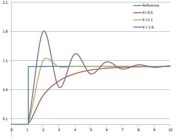
PID response shown graphically, by varying P

Excessive P (purple) produces oscillation. Low P (red) slowly rises to the setpoint. Optimal (green) settles quickly.

Delayed setpoint

A second situation is when your controller takes too long to get to the set point or never achieves the set point, but settles to a flow rate or pressure below the set point value. This implies either too small a P value being used or too large a damping influence. Using the analogy of a car, imagine you want to get to 70 miles per hour. but when you start increasing the speed, someone applies brakes which decreases the acceleration of the car. The car may never get to 70 mph if the deceleration is larger than acceleration, and the car may settle at a speed of 60 mph when acceleration = deceleration, or the opposite forces are equal.

In this case, try increasing your P value in 10-15% increments until you see the controller getting close to your set point. Next step would be to decrease the D value to help the controller get to the set point in a quicker time. If you start seeing some oscillations, that means the D value has been set too low.

Control loop adjustment is all about getting a good feel of how the controller responds to changes in the P and D terms. The gas viscosity, inlet pressure, back pressure can greatly influence how the valve responds. Tuning the valve is an art rather than science and the more familiar you get with your controller, the better you’ll be able to tune it.

Alicat promises lifetime customer support over the phone, so if you feel more comfortable with us helping you out with tuning, give us a call at 520-290-6060 and we’ll be more than happy to assist you.

Customizing mass flow and pressure controllers: brilliant to baroque

$
0
0

Many customers, even our most loyal ones, don’t realize that we customize just about EVERY Alicat instrument order. That’s because all our instruments are built when you order, and configured and programmed to best suit the application and conditions for which you’re buying them. Customizations can range from having a meter automatically tare itself every 24 hours, to engineering new limits of what our pressure controllers can handle! To give you an idea of how we work out your new requests, here are some simple and helpful customizations we produced on request.

Local Valve Drive Percentage

Resulting from a customization created at a customer’s request, the Local Valve Drive (LVD) option lets you monitor the work your valve is doing—because it can help you assess whether your process is in trouble. The LVD parameter appears on the large, multivariate display screen of an Alicat mass flow controller (or pressure controller), right above the main parameter output in the center. The LVD option reports the proportion of power being applied to the valve to maintain the setpoint. Valve drive percentage is something our devices normally track internally, and is a useful data point in troubleshooting, should you ever need it (our free lifetime support, available by phone or email, can help you with any troubleshooting you need). The value to the customer is that it serves as an indicator of the overall health of their chemical reactor vessel’s inputs and outputs. A significant change in the valve drive may indicate several possible failure conditions. Here’s a quick video showing this simple and smart customization at work:

Our “Local Valve Drive” (LVD) customization allows you to see how much drive is being given to a valve from your controller. One of our customers wanted a quick way to diagnose if their reactor’s output was dropping. Given steady pressures and flow rates, the valve drive will consistently be within a certain range. Our customer knew that at 30 PSIG inlet pressure with 10 SLPM of flow, the valve driver would be somewhere between 35-40% full power typically. If they saw the valve drive creeping much higher than this, then they would know that they were losing pressure differential in the process, since the valve was needing to open the valve wider than usual to create the same amount of flow. It may be that something is clogging the valve, making it open wider to allow flow to pass through. If they saw the valve drive percentage at 100 this would indicate that the valve was 100% open, or it was at least trying to be that way. They’d know that their reactors were creating such little output that it wasn’t possible to generate enough flow to satisfy their setpoint.

Local Valve Drive is now an option you can ask for, if your application calls for it.

Controlling pressurization speed

A customer wanted to use a pressure controller to maintain a certain pressure within a leak test chamber. However, they also wanted to make sure that the chamber would not pressurize too quickly.

MCD-Series bidirectional mass flow controller, shown with IPC option

MCD-Series bidirectional mass flow controller, shown with IPC option

To assure this, we built them a dual-valve mass flow controller in our MCD Series. A dual-valve mass flow controller can be programmed to fill with one valve and vent with a second valve. Like all our standard MFCs, it can be set to control flow based on pressure, rather than mass flow, (while still measuring mass flow!) Our dual-valve mass flow controller is also able to measure mass flowed in either direction. The MCD series of mass flow controller can be perfect for dispensing gases into a closed volume without overshooting or overpressurizing, or as an instantaneous pressurized leak test, with a built-in pressure relief valve for quickly changing the devices under test.

The customer used pressure control mode so that the setpoint was in pressure units, not mass flow units.

Finally, we created a custom software feature: a “Mass Flow Limit” function, configurable through the front screen. This would operate as a governor on the flow rate. It tells the valve to not open any further, once a certain mass flow rate was reached. This effectively limited how quickly the unit was allowed to pressurize their system.

Custom Configuring: a Stainless, IP-rated Dual Valve Pressure Controller

Customization can come in the form of unique combinations of options. Like this PCDS–it’s a dual valve pressure controller with a lot of options added on:

psds-ip65-remotevalve_lr

  • Stainless flow bodies and corrosion-resistant seals for using aggressive gases
  • A remote pressure sensor port (it’s on the backside of the flow body with the display), so that the pressure control will be based on a remote volume, independent of the valve lines.
  • IP-65, a liquid ingress prevention rating, means all the connectors are sealed with gaskets, and the display panel doesn’t have our menu buttons
  • The second valve is remote. The cable is the right length to mount the “relief” valve in a different location of the process flow.
  • Modbus industrial protocol on board. Without interface buttons to program the device, remote commands are necessary. But the display will provide a visual confirmation of the operation of the device for any technicians on the scene.

Altogether, it’s a very unusual device.

What’s your application?

When you place an order, our apps engineers always ask a lot of questions, like “What is the application? What are the operational parameters, and what are you trying to do?” This guides them in recommending things like custom tuning of valves (no extra charge!), or the selection of a particular sensor, or communications options. We do our best to make the device perform at its very best in your hands. Sometimes that means custom engineering, sometimes just custom configuring of existing options. Alicat prides ourselves in our ability to accommodate many custom configurations, or invent a solution!


Have questions?


Sign me up for the occasional newsletter.
Please leave this field empty.


About that Pressure Control Loop feature? It’s so cool

$
0
0

As an applications engineer at Alicat Scientific, I talk to people in every industry all over the world and learn about how they use our product. One of the most interesting applications I’ve seen is in a chemical reactor, where our mass flow controllers are used to control pressure and make sure that processes are repeatable.

Our flow controllers can be set to control on pressure while measuring mass flow. Our mass flow controllers measure volumetric flow rate, mass flow rate, temperature, and pressure. (It’s possible to control on any of those except temperature.) By controlling on pressure, you essentially have a pressure controller and mass flow meter in a single device. It’s a fairly unique option, and it takes a second to appreciate how valuable it can be.

Most other mass flow controllers don’t provide much flexibility, allowing only for control of mass flow. Take, for example, the pressure decay method to perform a leak check—you’ll use a pressure controller to set the pressure, stop the flow, and wait for pressure to decrease. Then you can perform calculations based on the exact volume and gas used. (This requires you to have extensive knowledge beforehand.) If you have a pressure controller with mass flow measurement, you’ll see the leak rate instantaneously—as soon as the pressure settles. This saves you time, calculations, and physical space, too.

Here’s a 47 second video to help you visualize it:

What is Closed Loop Pressure?

Closed loop pressure is our term for using a feedback loop based on pressure instead of mass flow. A mass flow controller will typically measure the mass flow and adjust the valve open or closed to increase/decrease the mass flow to the desired level. When controlling on pressure, the valve will adjust based on the pressure measurement. For example, let’s say you’re controlling pressure downstream of the Alicat and want to reach 100 psi. If you’re currently at 80 psi, the mass flow controller will open the valve further until the pressure reaches your set point. This is useful whenever you have an application where you want to control pressure and determine the flow rate. It could be leak checking, flow checking, or quality checking where you have a specific flow vs. pressure curve that needs to be met. Here, your end goal would be to keep variation within certain tolerances to make sure that the product meets your quality standards.

Hear Applications Engineer Alyssa Jenkins talk about the Pressure Control Loop feature in depth:

MCD With CLP and Totalizer

MCD closed volumeOur mass flow controller with dual valves, closed loop pressure, and totalizer is a bidirectional controller with three ports (inlet, process, outlet) and two valves: one with incoming flow and another separate exhaust valve. It can control a closed volume of pressure, meaning not only can one valve open or close to increase/decrease the flow rate, but it can also exhaust to atmosphere or vacuum pump if you overshoot the pressure. The totalizer measures the amount of flow that has occurred. There are four different ways to determine the total amount of flow using these bidirectional meters:

  1. Add positive flow and subtract negative, allowing the total flow to go negative
  2. Add positive flow and subtract negative, not allowing the total flow to go negative
  3. Add positive flow and ignore negative flow
  4. Add positive flow and subtract negative flow, resetting when it reaches 0

You’ll know how much is in that specific volume at any given time, which is important if you want to measure the amount of gases going into a system.

Using Alicat With Rotameters

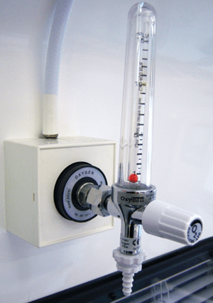
A rotameter has a floating indicator in a graduated tube.

A rotameter has a floating indicator in a graduated tube.

Rotameters measure volumetric flow rate, and they are tuned at a very specific pressure to give the mass flow rate. While they may be marked in standard liters per minute (slpm) or standard cubic centimeters per minute (sccm), this reading is only valid at the pressure for which the rotameter was tuned. An Alicat, on the other hand, is valid at all times because it has a pressure sensor that adjusts the reading when the pressure changes. Comparing rotameters to Alicats is like comparing apples to oranges because they are measuring different things, unless the rotameter is at it’s very specific calibrated pressure. However, since we can control pressure with an Alicat mass flow device, why not control to the pressure to which the rotameter is tuned?

We’re typically talking about the setting the pressure downstream of the rotameter, so it’s simply a matter of placing the Alicat downstream with the valve on the opposite side, so that you are controlling the back pressure from the valve, through the Alicat and the rotameter. Then you can measure the flow directly on the mass flow meter and the rotameter at the same time. Of course, you must make sure that the Alicat has the rotameter’s gas and standard conditions selected. They aren’t adjustable on the rotameter, but they are adjustable on the Alicat. You can choose from hundreds of gases (up to 130, but most standard series have 98 selectable options) along with user-selectable standard temperature and pressure.

Why Choose Alicat?

Solving unique problems is probably my favorite part of being an applications engineer. When it comes to Alicat products, everything can be customized to suit a customer’s needs. If a customer has a unique application that we haven’t seen before, the solution might involve making some small tweaks, like putting a valve in a different place or adding a relative humidity sensor. For instance, right now we’re figuring out how to work with 500 liters per minute of sulfur dioxide. Because it’s highly corrosive, we need to use 316 stainless steel and FFKM. One of my colleagues is also working on making our new IP or NEMA rated instruments more durable. We started a whole redesign of the system based on the input of a couple of customers.

If you have an application that you think might require a customized solution, call Alicat to speak with an applications engineer. We’ll answer your technical questions to the best of our ability and help you figure out if there is a custom solution we can build to meet your needs.


Precision & Repeatability in Fiber Optic Manufacturing

$
0
0

In the optical fiber industry, manufacturers’ needs center around precision and repeatability. It’s somewhat analogous to archery, where accuracy means hitting the bullseye. If you can hit the same point on the target every time, that’s precision. Repeatability is being able to demonstrate the same precision every time you walk up to the line and shoot. Let’s take a look at how optical fibers are manufactured, and where Alicat fits into the picture.

How Optical Fibers Are Manufactured

The fiber optic manufacturing process begins with the creation of a preform, where layers of very pure glass are built up on a rod. Different types of gases in very specific amounts are used to deposit a new glass layer on each pass, and every layer that is laid down on the base will give the end fiber a different property. A flame uses fuel gases, operated by a mass flow controller, to maintain a certain temperature and ensure the process is running optimally. The layering process sometimes takes place over the course of many hours depending on the size of the preform.

After the preform is created, it is then placed into a drawing tower. As one end of the preform is heated, inert gases are used to keep the heating element from burning up during the process. As the first drop falls from the melted end, a thin fiber is produced and then cools in a cooling tube filled with nitrogen as it descends through the tower.

The thickness is measured, quality is checked, and depending on the end use of the product, a coating process may apply a very thin polymeric or acrylic layer on the outside of the glass. This coating helps to protect the pure glass from environmental conditions and preserve the important properties within the glass fiber itself. Pressure control regulates the flow of this liquid polymer. In an extrusion-like process, it coats the fiber. Flow pressure needs extremely precise and repeatable control to provide a consistent coating over the product. Even a tiny amount of pressure fluctuation could lead to microns of variation in the overall thickness, which could dramatically affect the overall performance of the fiber. During the UV or Thermal curing, the material is keep in a an inert atmosphere to help the curing process. These gases are again controlled by mass flow controllers.

Depending on the size of the preform, it’s possible to run a fiber that spans anywhere from thousands of feet to hundreds of miles. We’re talking about pulling something to the width of a human hair and spooling it at 90 feet per second for hundreds of miles, while still maintaining uniformity. This is why the initial phase of making the preform is so important—to make a uniform product, the mass flow controllers must offer precise, repeatable controls of the gases that are used to deposit the different layers of glass.

Alicat’s Role in Fiber Optic Manufacturing

Fiber optic companies use Alicat products in several different aspects of the preform process and drawing process. During creation of the preform, we can be used for the burner control application, which controls the fuel gases which heat up the preform and help to control the deposition of each thin layer. We can also control the actual gases being used to create the very pure glass being deposited. And our mass flow controllers are used in the drawing process, where argon is being fed into the furnace area to keep the element from burning up. (The end result depends on the shape of the cone.)

About every five milliseconds, signals from our measurement sensors go through our entire processor. Depending on the type of process and operating pressures, the controller will have a control response of 50 milliseconds or less. (Sometimes we can help to tune that number down to sub-50 millisecond timeframes.) For anyone who might have a hard time imagining how fast this is, it takes the average human 300 to 400 milliseconds (thousandths of a second) to blink their eyes. Before you can even blink, our instruments have already obtained hundreds of measurements. To put that into perspective, in one second the gas burners and flow in the cooling tower may be adjusted over 200 times. That’s how we’re able to maintain repeatability and accuracy while a fiber is produced at 90 feet per second.

More Data Collection Means More Insight into the Process

Specialty fibers for high energy applications need to have very specific optical properties, which are shaped by the density and mix of materials. Therefore, depending on the part of the process, engineers want the ability to see as many parameters as possible. With an Alicat, you not only get the mass flow measurement, but also absolute pressure, volumetric flow, and temperature information so that you can refer back to it later. From a quality control perspective, you can use these parameters to determine what changed in the process and correlate that to a run that was rejected because of a defect.

Typically, the signals that provide this information go into some sort of a controller (a PLC) for interpretation. In case of a spike or a zero flow condition, the Alicat controller would send a signal to the PLC, which would then be able to shut down the line. Instead of having hundreds of feet or even miles of unusable product, it gives manufacturers the opportunity to identify that there’s a problem, get it fixed, and start the process again quickly.

Podcast of the interview for this post:

Compensating for Changing Environmental Conditions

Local environmental conditions can drastically affect the optical fiber manufacturing process. Unfortunately, we still find manufacturers that are used to the old way of doing things, where they don’t have the ability to adjust to changes in environmental conditions. For example, a particular manufacturer is located in an area that experiences heavy thunderstorms, which cause changes in barometric (atmospheric) pressure, and that causes an inconsistent product. With a storm in the neighborhood, they might decide not to even begin their 12-hour process, depending on the day’s forecast. Alicat can overcome and compensate for those changing atmospheric conditions and allow the manufacturer to produce high quality fiber—regardless of weather—because we measure flow in the context of pressure changes.

Other glass shaping processes

Mass flow instrumentation is used in many other glass processes besides fiber optics. Container manufacturers use mass flow controllers for regulating the gas flow to their melt process. There are also manufacturers that use mass flow to control the flame used to make fiberglass for structural components. Architectural glass is another huge consumer of mass flow controllers. They have an oven that’s hundreds of feet long, which requires precise temperature control to create a consistent glass product. (These are typically huge sheets of plate glass.) At any given zone of the oven, a specific temperature must be maintained with very precise flow control of fuel. Alicat mass flow controllers are deployed by architectural glass manufacturers to coat the glass to create different properties in the final product.

In the days before industrial automation was available, someone who gained years of expertise could determine the correct temperature just by looking at the color of the flame. They eventually learned how to make slight manual adjustments while walking down the line. What will the company do when those people retire? That’s where digital mass flow controllers come in—automation allows people to focus on developing optimal process conditions and monitoring parameters within the furnaces. Once everything is set up, it’s possible to know exactly what flow rates are needed to maintain the proper temperatures. The process is repeatable, and it provides useful data that can help identify why there may have been an inconsistency in the glass. The end result is greater repeatability, efficiency and a much better product.

To learn more, call Alicat to speak with one of our talented application engineers. They can answer pretty much any technical question you may have.

Reducing fluid control cost, complexity and inventory with Alicat MFCs

$
0
0

Controlling multiple pressures and managing differing gases can be critical to getting the data you need but multiple variables often means multiple instruments, adding complication and cost to your system. With one Alicat mass flow controller, you have the ability to simplify process controls—limiting error points—while increasing parameters monitored, and therefore saving you money on your next MFC installation.

Fewer Controllers for Large Flow Ranges

Let’s say you have to control flow over a large range, like 10 SLPM to 1000 SLPM. Most flow control solutions require two or more units to achieve accurate control over this range. Standard Alicat mass flow meters and controllers have a 200:1 turndown ratio. That means that where you normally deploy two MFCs to accomplish high and low range control in a system you might be able to replace those two MFCs with one Alicat MFC. With the turndown ratio of 200:1, a 1000SLPM Alicat MFC can control a range of 1000SLPM down to 5 SLPM. By eliminating a second controller, you reduce programming, and plumbing complexity—and most likely, you save money in the purchase.

Repurpose and Save Costs

With Alicat MFCs, each unit comes preprogrammed with 98 standard gases and gas mixtures, meaning if you need to service a controller, you don’t need an inventory of MFCs for each gas type, you can just keep one Alicat on hand. All you have to do is select the correct gas from the list and you’re good to go. No K factors to deploy, and no extra units to accommodate different viscosity gases—your mass flow rate stays accurate.

Process Insights from Multivariate Data

Alicat MFCs measure and report pressure, temperature, volumetric flow and mass flow. Having all of this information may allow you to eliminate one or two other instruments in your process and thereby reduce your overall instrumentation purchase costs even further. A side benefit to eliminating additional instruments is fewer leak points. And because Alicat MFCs use differential pressure measurement to obtain a mass flow rate, our MFCs can be set to control on pressure and still read mass flow. A single Alicat MFC can replace instrument duplication, providing you with a simpler, cost effective way to meet all your MFC needs.

All the ways

Alicat mass flow controllers simplify your setup while reducing overall instrumentation costs in your system because:

  • The 200:1 turndown ratio gives you a wider measurable control range.
  • One instrument can be repurposed to many gases.
  • Multivariate parameter measurements to obtain temperature, volumetric, mass, and pressure data.
  • Fewer instruments mean a lower cost of ownership cost over the life of the process.

Contact Alicat to build your simple, most effective and cost-saving fluid control process.

Have questions?


Sign me up for the occasional newsletter.
Please leave this field empty.


Four kinds of intelligent pressure control

$
0
0

From nitrogen purging or filter characterization, through vessel pressure control and leak testing applications, Alicat instruments are versatile and easy to use, while still providing excellent process control. This is because they operate with very fast control response (50-100 milliseconds) and high accuracy.

Our products are easy to program through a display interface, a serial connection or an analog connection, and we are dedicated to fast-turn-around on customized products to meet unique and variable specifications and requirements across industries. Pressure control applications can be enhanced by multivariate, rapid control, as demonstrated with these four examples.

Filter Characterization

An Alicat Pressure Controller can be used to set the pressure drop across the filter by measuring pressure before and after the filter while an Alicat mass flow meter can be used to measure the flow rate required to generate the needed pressure drop. Because mass in equals mass out, the flow meter can be placed upstream of the pressure controller as well.

Filter Test

Diagram 1

Diagram 1 illustrates a filter test using a differential pressure controller to regulate pressures before and after the filter while a mass flow meter measures flow-through at that pressure combination.

Manufactured Component Leak Characterization

Diagram 2

Diagram 2

Using an Alicat Mass Flow Meter and an Alicat Pressure Control Device, the user has a fast, accurate and reliable method for leak checking components. Our mass flow meters have full scale ranges as small as 0.5 sccm with 200:1 turndown ratio, meaning that flows as low as 0.0025 sccm (2.5 sμlm) can be resolved. If plumbed as shown in Diagram 2, the pressure is controlled at the entrance to the Device Under Test (DUT). A constant bleed though the needle valve allows the pressure controller to precisely hold the pressure at the DUT, ensuring that any flow through the meter after the bypass valve is closed is caused either by a leak or due to a cooling of the volume of the DUT. As long as the temperature of the DUT is constant, the flow reported at the meter will be the leak rate of the DUT.

High-Efficiency Helium Leak Testing

Alicat’s Dual Valve Pressure Controller is designed to prevent inefficient off gassing and to save costly gases like helium in closed-volume applications. In one kind of test, the pressure controller first removes all the air out of the test chamber then refills the chamber with helium to the desired test pressure. The gas analyzer records any helium that passes through the test device. The integrated exhaust valve of the pressure controller opens only when needed, so it maintains test pressures without continuously wasting gas through a bleed valve. See Diagram 3.

Helium leak testing using a dual valve pressure controller with pressure sensing to a helium chamber.

Diagram 3

Backpressure Control with Flow Monitoring

Backpressure control using a mass flow controller set to control on pressure.

Diagram 4

Instead of using a dedicated pressure controller and a separate mass flow meter, Alicat’s mass flow controllers (MFC) reduce equipment needs to a single instrument. This can be accomplished by setting the MFC to control for absolute pressure. The instrument will now control pressure while simultaneously displaying flow rates. As illustrated in Diagram 4, the mass flow controller allows pressure inside the system to build, simulating the internal pressure of a tire versus the air compressor that is attempting to fill it.

Conclusions

Specialized application engineering knowledge acquired by Alicat, for measuring and control techniques used in a wide spectrum of pressure and flow control processes, ensures that Alicat can quickly provide the optimum solution to your specific need and application, helping you create the most cost- and time-efficient system.

Have questions?


Sign me up for the occasional newsletter.
Please leave this field empty.


Why Recalibrate Your Alicat Device Annually?

$
0
0

When exact measurements and highly accurate data is critical to the success of an experiment, test, calibration or other application, maintaining a precisely calibrated device is key. To meet the demands put on them, we recommend that all Alicat meters and controllers are recalibrated annually.

When a device is sent in for recalibration it is an opportunity not only to maintain the quality and precision of the device, but also an opportunity to update firmware or, if your application needs have changed, the perfect time to work with our Application Engineers to find a solution that allows your Alicat to be adjusted or upgraded to meet your evolving needs without the hassle and expense of buying a whole new instrument.

Why Recalibrate?

Over time, minor physical changes to the laminar flow elements and pressure sensors inside the device, such as particulate deposits or damaged flow elements, can alter the flow characteristics of the device’s flow path. These altered flow characteristics can affect the pressures transmitted to the absolute and differential pressure sensors in the device’s flow body, causing the calibrated flow curve to inaccurately represent the actual flow rate. With an annual recalibration, out-of-calibration instruments are brought back to their optimal and exact calibration specifications and, if need be, can be cleaned.

Even if the device arrives at our factory or a service center within its prescribed flow tolerance, our service technicians recalibrate the device to be truer to the actual flow rates read by the calibration standard at the necessary calibration points. Alicat can also provide additional or replacement calibration points, if something other than the standard five calibration points is required. Additional calibration points or upgrade of accuracy to ‘high accuracy’ specification can be requested for instruments.

A calibration procedure is demonstrated in this video about accuracy:

Standard calibration typically takes fifteen business days to complete once the device arrives at one of our facilities. With such a quick turnaround time, you can be back to fully operational with a highly calibrated instrument with minimum interruption. For around the clock use of an Alicat, our Application Engineers will work with you to find a suitable and cost effective solution and the right back up device to keep the process running and the instruments in peak calibration.

If ISO-17025 calibration is required by your organization, Alicat can provide this kind of calibration through trusted third party calibration services. ISO-17025 calibration can add about 10 business days to the standard calibration lead time.

Sending your instrument back for recalibration every year keeps the lifetime warranty of your Alicat in place.

Where can Alicat instruments be calibrated?

We recommend that all devices come back to one of Alicat’s approved facilities for recalibration. Most devices will be recalibrated in our Tucson, Arizona headquarters and factory. However, if you are not located in North or South America, there may be a closer location you can send instruments for faster shipping. Alicat currently has service centers in China and India and has a factory authorized service center in Europe.

Getting recalibration started

More information about the costs and benefits of recalibration can be found on the Alicat website or by contacting one of our expert Applications Engineers. To send your instrument in for calibration to Alicat, fill out the service request form. The form lets us assign a Return of Materials Authorization (RMA) number, which is needed for us to receive and process your instruments at the factory. After sending in the form, we can send you instructions for packing and shipping your instruments.

FAQ: Recalibration of Alicat Devices

$
0
0

When do I need to get my Alicat device calibrated?

We recommend sending your units back for yearly calibration. This upholds your lifetime warranty and allows our service department to check for any damage to the device. Over time minor physical changes to the laminar flow elements and pressure sensors inside the device and particulate deposits can cause the instrument’s calibrated flow curve to inaccurately represent the actual characteristics of the flow path. With an annual recalibration, instruments are brought back to their optimal calibration specifications and, if need be, can be cleaned.

What is included in an annual recalibration?

Every recalibration starts with an evaluation.  Our service technicians will double check analog signals, settings, sensor health, LCD functionality, threads and even cosmetic issues like a scratch on the display.

After careful evaluation, our service technician will log “as found” data showing how precisely calibrated the unit was when it arrived. The device is then compared to our local barometric pressure and a NIST traceable standard and calibration adjustments are made to achieve the closest to ideal calibration possible. If anything is noticed to be out of sync, we work with the customers to make sure they understand the condition of their Alicat and how we will recalibrate and, if needed, repair the device.

Additional benefits of annual recalibration

When a device is sent in for recalibration it is an opportunity not only to maintain the quality and precision of the device, but also an opportunity to update firmware or, if your application needs have changed, the perfect time to work with our Application Engineers to find a solution that allows your Alicat to be adjusted or even customized to meet your evolving needs without the hassle and expense of buying a whole new instrument. Many reconfiguration options are available for Alicat devices—from updating the display to changing the flow range.

On the calibration certificate

Annual calibration includes a NIST traceable calibration certificate with before and after recalibration data. On the calibration certificate, we list certain parameters and conditions related to the calibration:

  • P/D/I values: These are the default tuning settings on the device. Note: most units will only have P and D settings.
  • Process gas: The pre-selected gas from the gas menu. This can be changed through the front panel or during recalibration.
  • Calibration gas: The gas used to calibrate the unit. Unless a customer specifically asks for an “actual gas calibration” we typically use air.
  • Range: The full scale range of the unit. Since we can configure devices with custom ranges, this may not match the body size found in the part number.
  • Gas temperature: The temperature of the gas that was used to calibrate the device at our facility.
  • Ambient humidity: The humidity of our facility at the time of calibration.
  • Calibration procedure/rev #: The standard procedure and revision used to calibrate the gas.

Below this there is a list of standard tools used to calibrate the unit. Every standard tool used to calibrate the units has an associated calibration chain, to keep all units NIST traceable. This list shows our standard tool’s name, that tool’s calibration due date, manufacturer and model number and uncertainty. Some units listed in this section are Alicat units. These are primary transfer standards, with high accuracy calibration. They are used for calibrating devices to our standard (as opposed to “high”) accuracy procedures.

For recalibrations, you will also get as found and as left data. This lets you know if the unit was in spec when it arrived at the calibration facility, and if not, which points were out of tolerance. This also shows the uncertainty, calibration pressure and units of measure. In the “as found” and “as left” sections, the “D.U.T.” is your Alicat device being calibrated and “Actual” is the reading from the high accuracy device it is being compared to. The outputs are the analog inputs and outputs.

How do I get a recalibration from Alicat?

To order a calibration through Alicat, use the service request form. On receipt of your request, we’ll issue you an RMA (Return of Materials Authorization) and send you shipping instructions. If you’re close to one of our regional calibration or service centers, you should contact that center for an RMA.

Viewing all 50 articles
Browse latest View live